"People call me simple-minded. I prefer decisive. There are exactly two kinds of pixels in this world, and I have never once been unsure which kind I am."
A Strictly Binary Pixel
The moment an image becomes binary, it stops being a grid of measurements and becomes a set of pixels, and every question about objects (how many, how big, touching or separate) reduces to set membership plus one deceptively deep definition: which pixels count as neighbors. This section builds that foundation: binary images as sets, the 4- and 8-neighborhoods, the connectivity paradox that forces foreground and background to use different definitions, and the grid distances that the rest of the chapter, from structuring elements to distance transforms, is built on.
The previous chapter ended with a small triumph: the document scanner of Chapter 5 rectified a photographed page and binarized it into crisp black text on white. The thresholding machinery of Chapter 2 can do the same to a backlit machine part, a microscope slide, or a segmentation model's probability map. In every case we are left holding the same object: a binary image. Before we can clean it, count it, or measure it, we need vocabulary precise enough to survive contact with corner cases. That vocabulary, digital topology, is the business of this section, and it contains one of the best surprises in elementary computer vision: the obvious definition of "connected" is mathematically broken, and the fix is delightfully odd. The illustration below sets the tone: the humble tools of this chapter still do most of the world's real inspection work.

1. From Measurements to Sets Beginner
A binary image assigns each pixel one of two values. Everything in this chapter flows from a change of perspective: instead of treating it as a function $I(x, y) \in \{0, 1\}$, treat it as a set. The foreground is the set of pixel coordinates where the image is on,
$$ A \;=\; \{\, (x, y) \;:\; I(x, y) = 1 \,\}, $$
and the background is its complement $A^c$. The payoff is that operations on objects become operations on sets: union, intersection, complement, and translation. When Section 6.2 defines erosion and dilation, the definitions will be one line of set notation each, and properties like duality will follow from set algebra rather than from staring at pixels.
In code, two storage conventions coexist, and mixing them up is the most common beginner bug in this chapter. OpenCV represents binary images as uint8 arrays holding 0 and 255 (so they display correctly and feed directly into its C++ kernels), while scikit-image and SciPy prefer boolean arrays of False and True. Beyond storage, a second convention decides which of the two values counts as the object. The universal rule, inherited from morphology's origins in microscopy: foreground is white (nonzero), background is black. A scanned page violates this (ink is dark), so the standard first move is to threshold with inversion. The snippet below shows both conventions and the inversion, using Otsu's method from Chapter 2 without re-introduction.
# Binarize a scanned page (dark ink) and inspect both storage conventions:
# OpenCV's 0/255 uint8 versus the boolean masks scikit-image and SciPy expect.
# The final lines recover the set-theoretic foreground used by this chapter.
import cv2
import numpy as np

page = cv2.imread("scanned_page.png", cv2.IMREAD_GRAYSCALE)

# Ink is dark, so invert during thresholding: foreground must be white.
_, mask = cv2.threshold(page, 0, 255,
                        cv2.THRESH_BINARY_INV + cv2.THRESH_OTSU)

print(mask.dtype, mask.min(), mask.max())   # uint8 0 255  (OpenCV convention)

mask_bool = mask > 0                         # scikit-image / SciPy convention
print(mask_bool.dtype)                       # bool

# The set-theoretic view: foreground as coordinates.
ys, xs = np.nonzero(mask_bool)
print(f"|A| = {len(xs)} foreground pixels "
      f"({100 * mask_bool.mean():.1f}% of the image)")
# Representative output:
# uint8 0 255
# bool
# |A| = 184302 foreground pixels (8.8% of the image)uint8 and the boolean arrays preferred by scikit-image, plus the coordinate-set view that the chapter's mathematics is written in.
One practical warning before moving on: a boolean array passed to an OpenCV function will usually raise an error or silently misbehave, and a 0/1 uint8 array (rather than 0/255) will display as solid black in any viewer while still being a perfectly valid mask. When a morphology pipeline produces baffling results, the first check is always dtype, the value range, and which side is white.
2. Neighborhoods: Who Counts as Adjacent? Beginner
Sets alone are not enough; objects are about pixels sticking together, and that requires deciding which pixels are neighbors. On a square grid there are two natural answers. The 4-neighborhood $N_4(p)$ of a pixel $p = (x, y)$ contains the pixels that share an edge with it: $(x \pm 1, y)$ and $(x, y \pm 1)$. The 8-neighborhood $N_8(p)$ adds the four diagonal pixels that share only a corner, the set sometimes written $N_D(p)$, so that $N_8(p) = N_4(p) \cup N_D(p)$. Figure 6.1.1 draws both.
From adjacency comes the central definition. A path from pixel $p$ to pixel $q$ within a set $S$ is a sequence of pixels $p = p_0, p_1, \ldots, p_n = q$, all belonging to $S$, where each consecutive pair is adjacent under the chosen neighborhood. Two pixels are connected in $S$ if such a path exists, and a connected component is a maximal subset of mutually connected pixels: an "object." Everything Section 6.4 does, labeling, counting, and measuring blobs, is the algorithmic realization of this definition. The choice of neighborhood is not cosmetic: a one-pixel-wide diagonal line is a single object under 8-connectivity and a scatter of $n$ isolated pixels under 4-connectivity, because consecutive diagonal pixels share corners but never edges.
3. The Digital Jordan Curve Paradox Intermediate
So which neighborhood is correct? Here digital topology delivers its famous surprise. In the continuous plane, the Jordan curve theorem guarantees that any simple closed curve separates the plane into exactly two regions, an inside and an outside. A sensible digital geometry should preserve this. Neither uniform choice does.
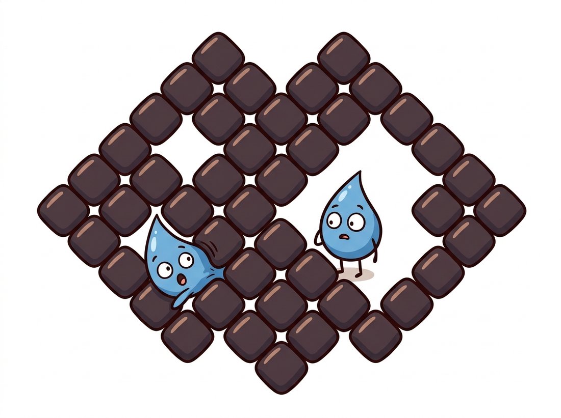
Consider a closed loop of foreground pixels arranged as a diamond, where each consecutive pair of loop pixels touches diagonally. Under 8-connectivity the loop is a perfectly good closed curve. But its background is also 8-connected, and a background path can slip diagonally between two diagonal loop pixels, crossing the curve without touching it. The inside leaks out: a closed curve that fails to enclose anything. Switch both to 4-connectivity and the opposite absurdity appears: the loop shatters into isolated fragments (no two diagonal pixels are 4-adjacent), yet those disconnected fragments still manage to separate the 4-connected background into an inside and an outside. A curve that is not connected separates the plane; a curve that is connected does not. Figure 6.1.2 shows the leak, and the illustration below tells the same story with a trapped character slipping through a corner gap.
The resolution, formalized by Azriel Rosenfeld in his founding papers on digital topology around 1970, is to treat foreground and background asymmetrically: if foreground objects use 8-connectivity, background must use 4-connectivity, and vice versa. With the complementary pair, every digital closed curve separates inside from outside exactly as Jordan promised. The convention used almost everywhere in practice, and the default in OpenCV's contour and component machinery, is 8-connected foreground, 4-connected background, which matches human intuition that a diagonal pen stroke is one stroke.
There is no single correct adjacency on a square grid; there is only a consistent pair. Choose 8-connectivity for foreground when thin diagonal structures (cracks, wires, pen strokes) must hold together, and accept that holes are then defined 4-connectedly. Every algorithm later in this chapter (labeling in Section 6.4, hole counting, contour hierarchies in Section 6.6) silently bakes in this pair, and two libraries with different defaults will report different object counts on the same mask.
The paradox is observable in eleven lines. The code below builds the diamond ring of Figure 6.1.2 and lets cv2.connectedComponents count objects under each connectivity, for the ring itself and for its background.
# Build the diamond ring of Figure 6.1.2 and count its components under each
# connectivity, for both the ring (foreground) and its background. Only the
# mixed 8/4 convention makes a closed curve actually enclose its interior.
import cv2
import numpy as np

yy, xx = np.mgrid[0:9, 0:9]
ring = ((np.abs(xx - 4) + np.abs(yy - 4)) == 3).astype(np.uint8)  # diamond loop

for conn in (8, 4):
    n_fg, _ = cv2.connectedComponents(ring, connectivity=conn)
    n_bg, _ = cv2.connectedComponents(1 - ring, connectivity=conn)
    # retval includes label 0, so subtract 1 to count true components
    print(f"connectivity={conn}: ring pieces = {n_fg - 1}, "
          f"background regions = {n_bg - 1}")
# Output:
# connectivity=8: ring pieces = 1, background regions = 1   <- inside leaks out!
# connectivity=4: ring pieces = 12, background regions = 2 <- curve in fragments4. Distances on the Grid Intermediate
Each neighborhood induces a notion of distance: the length of the shortest path between two pixels, stepping only between neighbors. Stepping through $N_4$ gives the city-block distance (count edge moves), stepping through $N_8$ gives the chessboard distance (diagonal moves cost the same as straight ones, exactly a chess king's move count), and the familiar Euclidean distance sits between them:
$$ d_4(p, q) = |\Delta x| + |\Delta y|, \qquad d_8(p, q) = \max(|\Delta x|, |\Delta y|), \qquad d_E(p, q) = \sqrt{\Delta x^2 + \Delta y^2}, $$
with the ordering $d_8 \le d_E \le d_4$ for every pair of pixels. The geometric fingerprint of each metric is its unit "disk," the set of pixels within distance $r$ of a center: a diamond for $d_4$, a square for $d_8$, and a discretized circle for $d_E$. Those three disks will reappear almost immediately: they are the cross, square, and ellipse structuring elements of Section 6.2, and they are the level sets of the three distance-transform variants in Section 6.5. Before drawing the disks, a quick computation makes the gap between the metrics concrete:
# Evaluate the three grid metrics on one pixel displacement to expose the
# sandwich d8 <= dE <= d4: chessboard undershoots the true diagonal distance,
# city-block overshoots it, and Euclidean sits between them.
import numpy as np

p, q = np.array([0, 0]), np.array([5, 3])
d = q - p
print("city-block d4 =", np.abs(d).sum())          # 8
print("chessboard d8 =", np.abs(d).max())          # 5
print("euclidean dE =", float(np.hypot(*d))) # 5.830951894845301Each metric's unit disk is the geometric signature that the rest of the chapter inherits. Figure 6.1.3 places the three side by side, every shaded cell being a pixel within distance $2$ of the center under that metric.
Why tolerate three metrics instead of just using Euclidean everywhere? Speed and exactness trade off. The path-based metrics $d_4$ and $d_8$ propagate across an image in two simple sweeps (the chamfer algorithm of Section 6.5), while exact Euclidean distance requires cleverer machinery. For decisions like "is this blob within 3 pixels of that one," chessboard distance is usually accurate enough and dramatically cheaper, a trade-off with the same flavor as the separable-filter economics of Chapter 3.
5. Library Conventions: The Silent Disagreements Beginner
The Python imaging stack assembled in Chapter 0 contains three mature implementations of connected components, and they do not agree on defaults. cv2.connectedComponents defaults to 8-connectivity. skimage.measure.label also defaults to full connectivity (8 in 2D) but exposes it as connectivity=2, meaning "neighbors may differ in up to 2 coordinates." scipy.ndimage.label defaults to 4-connectivity via its cross-shaped structuring element. Run all three on the same diagonal-rich mask and you can get three different object counts, none of them a bug.
Identifying connected components from the path definition requires a hand-written flood fill or union-find pass, roughly 30 lines that Section 6.4 writes out for understanding. In production it is one line in any of the three libraries: cv2.connectedComponents(mask, connectivity=8), skimage.measure.label(mask, connectivity=2), or scipy.ndimage.label(mask, structure=np.ones((3,3))). The libraries handle label compaction, cache-friendly memory traversal, and (in OpenCV's case) SIMD-parallel two-pass algorithms benchmarked in the YACCLAB suite. The only thing they cannot do is choose your connectivity for you: always pass it explicitly, precisely because the defaults disagree.
Who: A two-person vision team at a semiconductor packaging plant, inspecting X-ray images of wire bonds inside chip packages.
Situation: Their pipeline thresholded each X-ray (using adaptive methods from Chapter 2), labeled the bright wire structures, and flagged any package whose wire count differed from the schematic. It had run reliably for a year on one product line.
Problem: On a new package layout, the system began rejecting nearly every unit, reporting 40 to 60 wires where the schematic said 14. The wires in the new layout ran at 45 degrees across the sensor grid, and a recent refactor had swapped the labeling call from OpenCV to scipy.ndimage.label with its default 4-connectivity. Each one-pixel-wide diagonal wire image shattered into dozens of single-pixel "wires."
Decision: Pass an explicit 8-connected structuring element (np.ones((3, 3))) to scipy.ndimage.label, and add a unit test: a synthetic diagonal line must always label as exactly one component, in every library the codebase touches.
Result: Counts returned to 14, the false-reject rate fell from 97 percent to under 0.5 percent, and the unit test later caught the same regression when a third library was introduced.
Lesson: Connectivity is an argument, not a constant of nature. Any pipeline that counts objects should pin it explicitly and test it on a diagonal line, the canonical input on which the two conventions diverge.
An alternative fix for the Jordan paradox is to abandon the square grid entirely. On a hexagonal grid every neighbor shares an edge, there are no corner-only adjacencies, one connectivity works for foreground and background alike, and the paradox never arises. Hexagonal sensors and sampling schemes have been proposed regularly since the 1960s, and the human retina itself packs photoreceptors hexagonally. Square pixels won anyway, for the least topological reason imaginable: rectangular arrays were easier to manufacture and address.
6. Where This Foundation Leads Beginner
It is worth pausing on how much is now in place. A binary image is a set; neighborhoods make it a graph; connectivity carves the graph into objects; distances measure the geometry of those objects. The next two sections add the missing ingredient, operators that reshape the sets: erosion and dilation in Section 6.2, and their compositions in Section 6.3. The definitions established here are not merely classical trivia, either. When the segmentation networks of Chapter 24 output a probability per pixel, thresholding that map produces precisely the binary sets of this section, and the post-processing applied to them (hole filling, small-object removal, component counting) runs on the definitions fixed here. The watershed and graph-based methods of Chapter 11 likewise inherit this section's adjacency graphs wholesale.
Digital topology has moved from post-processing into the training loop. Standard per-pixel losses happily break a vessel or road into pieces if most pixels are classified correctly, so a wave of topology-aware losses now penalizes connectivity errors directly: clDice (Shit et al., CVPR 2021) matches skeletons between prediction and ground truth, Skeleton Recall Loss (Kirchhoff et al., ECCV 2024, arXiv:2404.03010) makes that practical at scale for thin tubular structures, and Efficient Betti Matching (Stucki et al., 2024, arXiv:2407.04683) optimizes the persistent-homology structure of the prediction so that the number of components and holes, the exact quantities defined in this section, matches the annotation. The 1970s definitions of Rosenfeld are now differentiable training signals for 2026 segmentation networks.
The smallest image exhibiting the connectivity paradox is the $2 \times 2$ checkerboard: foreground at the top-left and bottom-right pixels, background at the other two. Work through all four connectivity assignments (foreground/background each 4 or 8) and state, for each, how many foreground components and background components exist. Which assignments allow the two foreground pixels and the two background pixels to both form connected sets, and why is that geometrically absurd (think about the two "curves" crossing)?
Generate random binary images ($512 \times 512$) where each pixel is foreground independently with probability $p$, for $p$ from 0.30 to 0.70 in steps of 0.02. For each $p$, count foreground components under 4- and 8-connectivity (average over 10 trials) and plot both curves. You should see the component count peak and then collapse as blobs merge. At what $p$ does a single component first span the image edge to edge under each connectivity? (This threshold is the site-percolation threshold, near 0.5927 for 4-connectivity; observe how 8-connectivity shifts it.)
Prove the inequality chain $d_8(p,q) \le d_E(p,q) \le d_4(p,q) \le 2\, d_8(p,q)$ for all pixel pairs, and identify the displacement directions where each inequality becomes an equality. Then compute the worst-case relative error of $d_8$ as an estimate of $d_E$ (it occurs on the diagonal) and explain why Section 6.5's chamfer transform mixes edge steps of cost 3 with diagonal steps of cost 4 to shrink that error.